A
prototype of gravimetric gradiometer
Gravimetric prospection is a widely
used method for geological structures studies, in particular for mining and oil
researches. Significant results require the use of instrumentation with a high
level of sensitivity and accuracy, of the order of the microGal (1µGal=1 cm/s2)
that is 10-9 g. At this sensitivity level spurious
effect become important, that are not connected with underground mass
distributions, but that are due to surface topographic irregularities or to
anthropic activities or to tidal fluctuations. The instrumental drift,
unavoidable in mechanical sensors because of creep of the elastic elements,
thermal gradients etc., is another source of errors, which becomes more and
more important as the survey length increases. This difficulties can be
overcome by using gradiometric methodology, where the observed datum is a
component of the g gradient tensor, calculated as the difference of the g
values measured at the same instant at the extremes of a fixed basis
distance.
Our apparatus consists of two
identical accelerometric sensors, placed vertically one over the other at a
fixed distance of the order of 25 cm.,
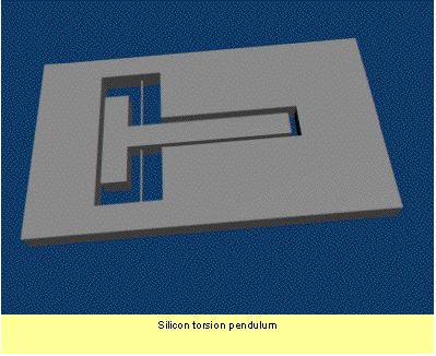
The individual sensor is shown in
fig.1: a bar of crystalline Silicon of about 4 mm of thickness, is carved by
ultrasonic machining in order to produce a torsion pendulum, joint to the fixed
structure by two thin torsion beams (0.6 – 0.7 mm) with a length of about 10
mm. At the lever extremity, though a cylindrical rod, a sapphire disk is stuck.
This is the mobile part of the sensor, which will have a mechanical resonance
frequency of 20 –30 Hz.

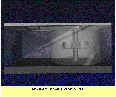
The
torsion pendulum is bended by the gravity, approaching the sapphire disk to a
second sapphire disk, which is fixed to the sensor frame. The dimensions are regulated so that,
for standard g values, the distance is about 100 µm. The variation of g values
is monitored at very high resolution by measuring the resonance frequency of
a “whispering gallery” mode
of the resonator made by the two sapphire disks. For the modes that fall in the microwave region, near 10 –
11 GHz, the distance variation/frequency drift transferring factor ∂f/∂x has
been measured greater than 5 MHz/µm, A gravity gradient of 1 Eötvös (10-9
s-2), measured with two sensors placed at a distance of 20 cm one
from the other, is correspondent to a differential equilibrium displacement of
the two pendulums dx = 1.25
10-14 m, equivalent to about 0.06 Hz.
 This
frequency difference will be directly read by comparing in an interferometer
phase detector circuit the resonance frequency of the two cavities. The
interrogating microwave oscillator uses one of the cavities as feedback
impendence, so that an efficient common mode rejection rate of external
perturbation noise can be achieved by a balancing of electrical and mechanical
properties of the two sensors as perfect as possible.
This
frequency difference will be directly read by comparing in an interferometer
phase detector circuit the resonance frequency of the two cavities. The
interrogating microwave oscillator uses one of the cavities as feedback
impendence, so that an efficient common mode rejection rate of external
perturbation noise can be achieved by a balancing of electrical and mechanical
properties of the two sensors as perfect as possible.