(plus
the inputs), and a good choice of how to encode the state often
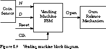
leads to a simpler implementation. Understanding the Problem The first step in the finite state machine design process is to understand the problem. Start by drawing a block diagram to understand the inputs and outputs.
Figure 8.9 is a good example. N is asserted for one clock period
when a nickel is inserted into the coin slot. D is asserted when
a dime has been deposited. The machine asserts Open for one clock period
when 15 cents (or more) has been deposited since
the last reset.
The specification may not completely define the behavior
of the finite state machine. For example, what happens if someone inserts
a penny into the coin slot? Or what happens after the gum is delivered to
the customer? Sometimes we have to make reasonable assumptions. For the
first question, we assume that the coin sensor returns any coins it does
not recognize, leaving N and D unasserted. For the latter,
we assume that external logic resets the machine after the gum is delivered.
Abstract Representations Once you
understand the behavior reasonably well, it is time to map the specification
into a more suitable abstract representation. A good way to begin is
by enumerating the possible unique sequences of inputs or configurations
of the system. These will help define the states of the finite state machine.
For this problem, it is not too difficult to enumerate
all the possible input sequences that lead to releasing the gum:
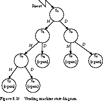
For example, the machine will pass through the states S0, S1, S3, S7 if the input sequence is three nickels.
To keep the state diagram simple and readable, we include
only transitions that explicitly cause a state change. For example, in state
S0, if neither input N or D is asserted, we assume
the machine remains in state S0 (the specification
allows us to assume that N and D are never asserted at
the same time). Also, we include the output Open only in states
in which it is asserted. Open is implicitly unasserted in any other state.
State Minimization This nine-state
description isn't the "best" possible. For one thing, since states
S4, S5, S6, S7, and S8 have
identical behavior, they can be combined into a single state.
To reduce the number of states even further, we can think
of each state as representing the amount of money received so far. For example,
it shouldn't matter whether the state representing 10 cents was reached
through two nickels or one dime.
A state diagram derived in this way is shown in Figure 8.11.
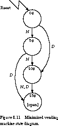
We capture the behavior in only four states, compared with nine in Figure
8.10. Also, as another illustration of a useful shorthand, notice the transition
from state 10˘ to 15˘. We interpret the notation "N,
D" associated with this transition as "go to state 15˘
if N is asserted OR D is asserted."
In the next chapter, we will examine formal methods for
finding a state diagram with the minimum number of states. The process of
minimizing the states in a finite state machine description is called state
minimization.
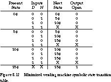
State Encoding At this point, we have a finite state machine with a minimum number of states, but it is still symbolic. See Figure 8.12 for the symbolic state transition table. The next step is state encoding.
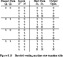
The way you encode the state can have a major effect on the amount of hardware you need to implement the machine. A natural state assignment would encode the states in 2 bits: state 0˘ as 00, state 5˘ as 01, state 10˘ as 10, and state 15˘ as 11. A less obvious assignment could lead to reduced hardware. The encoded state transition table is shown in Figure 8.13.
In Chapter 9 we present a variety of methods and computer-based tools for finding an effective state encoding.
Implementation The next step is to implement the state transition table after choosing storage elements. We will look at implementations based on D and J-K flip-flops.
The K-maps for the D flip-flop implementation are shown in Figure 8.14.
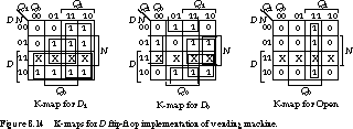
We filled these in directly from the encoded state transition table. The minimized equations for the flip-flop inputs and the output become
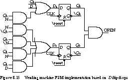
The logic implementation is shown in Figure 8.15. It uses eight gates and two flip-flops.
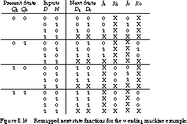
To implement the state machine using J-K flip-flops, we must remap the next-state functions as in Chapter 7. The remapped state transition table for J-K flip-flop implementation is shown in Figure 8.16.
We give the K-maps derived from this table in Figure 8.17.
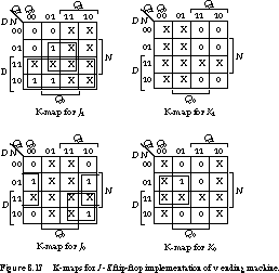
The minimized equations for the flip-flop inputs become
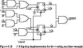
Figure 8.18 shows the logic implementation. Using J-K flip-flops moderately reduced the hardware: seven gates and two flip-flops.
Discussion We briefly described
the complete finite state machine design process and illustrated it by designing
a simple vending machine controller. Starting with an English-language statement
of the task, we first described the machine in a more formal representation.
In this case, we used state diagrams.
Since more than one state diagram can lead to the same
input/output behavior, it is important to find a description with as few
states as possible. This usually reduces the implementation complexity of
the finite state machine. For example, the state diagram of Figure 8.10
contains nine states and requires four flip-flops for its implementation.
The minimized state -diagram of Figure 8.11 has four states and can be implemented
with only two flip-flops.
Once we have obtained a minimum finite state description,
the next step is to choose a good encoding of the states. The right choice
can further reduce the logic for the next-state and output functions. In
the example, we used only the most obvious state assignment.
The final step is to choose a flip-flop type for the
state registers. In the example, the implementation based on D
flip-flops was more straightforward. We did not need to remap the flip-flop
inputs, but we used more gates than the J-K flip-flop
implementation. This is usually the case.
Now we are ready to examine some alternatives to the
state diagram for describing finite state machine behavior.
[Top] [Next]
[Prev]