
(for example, an ASM chart,
a state diagram, a VHDL program, or an ABEL description). In
this section we will illustrate the process by examining several detailed
case studies: an FSM that can recognize patterns in its inputs, a complex
counter, a traffic light controller, and a digital combination lock.(X) and one output (Z).
The output is asserted whenever the input sequence 010 has been observed,
as long as the sequence 100 has never been seen."
In the first pair of input/output strings, we find three overlapping
instances of 010 (0101010) before detecting the
termination string (100). Once this is found,
additional 010 strings in the input cause no changes in the output. We have
written the outputs so they lag behind the inputs. This is the kind of 0000timing
we would expect to see in the real machine.
Similar behavior is illustrated in the second pair of
strings. The detected sequence 010 is immediately followed by another 0.
Since this is the terminating string, the output stays at 0 despite further
010 strings in the input.
Formal Representation Now that we
understand the desired behavior of the finite state machine, it is time
to describe its function by a state diagram or ASM chart. Suppose we choose
to represent this example FSM with a state diagram for a Moore machine.
It is a good idea to start by drawing state diagram fragments for the strings
the machine must recognize: 010 and 100.
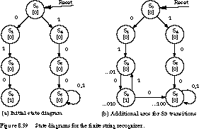
Figure 8.39(a) shows the initial Moore state
diagram, assuming state 0 is reached on an external reset signal.
One path in the diagram leads to a state with the output asserted when the
string 010 has been encountered. The other path leads to a looping state
for the string 100.
Given that there is only one input, each state should
have two exit arcs: when the input is 0 and when it is 1. To refine the
state diagram, the trick is to add the remaining arcs, and perhaps additional
states, to make sure the machine recognizes all valid strings.
For example, what happens when we exit state S3?
To get to S3, we must have recognized the string 010. If the next
input is 0, then the machine has seen 0100, the termination string. The
correct next state is therefore S6, our termination looping state.
What if the input had been a 1 in state S3?
Then we have seen the string 0101. This is a prefix of 010 if the next input
turns out to be a 0. We could introduce a new state to represent this case.
However, if we carefully examine the state diagram, we find that an existing
state, S2, serves the purpose of representing all prefix strings
of the form 01. The new transition from S3 to S2 is shown
in Figure 8.39(b).
Continuing with this approach, let's examine S1.
You should realize that any number of zeros before the first 1 is a possible
prefix of 010. So we can loop in this state as long as the input is 0. We
define S1 to represent strings of the form 0 before a 1 has been
seen.
State S4 plays a similar role for strings of
1's, which may represent a prefix of the terminating string 100. So we can
loop in this state as long as the input is 1. The next refinement of the
state diagram, incorporating these changes, is shown in Figure 8.40(a).
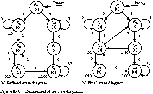
We still have two states with incomplete transitions:
S2 and S5. S2 represents strings of the form
01, a prefix of the string 010. If the next input is a 1, it can no longer
be a prefix of 010 but instead is a prefix of the terminating string 100.
Fortunately, we already have a state that deals with this case: S4.
It stands for strings whose last input was a 1 which may be a prefix of
100. So all we need to do is add a transition arc between S2 and
S4 when the input is a 1.
The final state to examine is S5. It represents
strings consisting of a 1 followed by a 0. If the next input is a 1, the
observed string is of the form 101. This could be a prefix for 010. S2
already represents strings of the form 01. So we add the transition between
S5 and S2 when the input is a 1.
We show the completed state diagram in Figure 8.40(b).
You should run through the sample input strings presented at the beginning
of this subsection to make sure you obtain the same output behavior. It
is always a good strategy to check your final state diagram for proper -operation.
ABEL Description It is straightforward
to map the state diagram of Figure 8.40(b) into
an ABEL finite state machine description. The description becomes
module string

title '010/100 string recognizer state machine

	 Joe Engineer, Itty Bity Machines, Inc.'

u1   device   'p22v10';
"Input Pins

	clk, X, RESET   pin   1, 2, 3;
"Output Pins

	Q0, Q1, Q2, Z   pin   19, 20, 21, 22;

	Q0, Q1, Q2, Z   istype 'pos,reg';
"State registers

SREG = [Q0, Q1, Q2, Z];

S0   = [0,0,0,0];  " Reset state

S1   = [0,0,1,0];  " strings of the form ...0

S2   = [0,1,0,0];  " strings of the form ...01

S3   = [0,1,1,1];  " strings of the form ...010

S4   = [1,0,0,0];  " strings of the form ...1

S5   = [1,0,1,0];  " strings of the form ...10

S6   = [1,1,0,0];  " strings of the form ...100
equations

	[Q0.ar, Q1.ar, Q2.ar, Z.ar] = RESET;	"Reset to S0
state_diagram SREG

state S0: if X then S4 else S1;

state S1: if X then S2 else S1;

state S2: if X then S4 else S3;

state S3: if X then S2 else S6;

state S4: if X then S4 else S5;

state S5: if X then S2 else S6;

state S6: goto S6;
test_vectors ([clk, RESET, X] -> [Z])

	[0,1,.X.] -> [0];

	[.C.,0,0] -> [0];

	[.C.,0,0] -> [0];

	[.C.,0,1] -> [0];

	[.C.,0,0] -> [1];

	[.C.,0,1] -> [0];

	[.C.,0,0] -> [1];

	[.C.,0,1] -> [0];

	[.C.,0,0] -> [1];

	[.C.,0,0] -> [0];

	[.C.,0,1] -> [0];

	[.C.,0,0] -> [0];

end string;
Since the finite state machine is encoded in seven states,
(at least) three registers must be assigned for
its representation. These are named Q0, Q1, and Q2.
The output Z is also registered and forms part of the state encoding.
This is shown in the state register description section.state_diagram
section, using simple IF-THEN-ELSE and GOTO statements. For example, if
the FSM is currently in state S0 and the input X is 1,
the machine's next state is S4. If the input is 0, the next state
is S1.test_vectors section first verifies
that the machine should output a 0 when reset. It then presents the machine
with the sample input string 00101010010 to check that the expected output,
00010101000, is -obtained.= 0, the
counter steps through the binary sequence 000, 001, 010, 011, 100, 101,
110, 111, and repeat. When m = 1, the counter advances
through the Gray code sequence 000, 001, 011, 010, 110, 111, 101, 100, and
repeat." Mode Input(M) | Current State | | Next State(Z2 Z1 Z0) |
|---|---|---|---|
| 0 | 000 | | 001 |
| 0 | 001 | | 010 |
| 1 | 010 | | 110 |
| 1 | 110 | | 111 |
| 1 | 111 | | 101 |
| 0 | 101 | | 110 |
| 0 | 110 | | 111 |

Figure 8.41 shows the state diagram. The states are named according to
the binary encoding of the state's output. State S0 has output
000, state S2 has output 010, and so on. Reset places the finite
state machine into state S0.
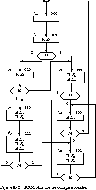
The equivalent ASM chart is shown in Figure 8.42. It
looks very much like a flowchart you might use to implement a program with
the specified input/output behavior. For example, when in state S1,
if M is 0, the next state is S2, otherwise the next state
is S3.
ABEL Description The machine's
state sequencing is quite easy to capture in terms of IF-THEN-ELSE descriptions.
The ABEL description -follows:
module counter

title 'combination binary/gray code up-counter

	 Joe Engineer, Itty Bity Machines, Inc.'

u1   device   'p22v10';
"Input Pins

	clk, M, RESET   pin   1, 2, 3;
"Output Pins

	Z0, Z1, Z2      pin   19, 20, 21;

	Z0, Z1, Z2      istype 'pos,reg';
"State registers

SREG = [Z0, Z1, Z2];

S0   = [0,0,0];

S1   = [0,0,1];

S2   = [0,1,0];

S3   = [0,1,1];

S4   = [1,0,0];

S5   = [1,0,1];

S6   = [1,1,0];

S7   = [1,1,1];
equations

	[Z0.ar, Z1.ar, Z2.ar] = RESET; "Reset to state S0
state_diagram SREG

state S0: goto S1;

state S1: if M then S3 else S2;

state S2: if M then S6 else S3;

state S3: if M then S2 else S4;

state S4: if M then S0 else S5;

state S5: if M then S4 else S6;

state S6: goto S7;

state S7: if M then S5 else S0;
test_vectors ([clk, RESET, M] -> [Z0, Z1, Z2])

	[0,1,.X.] -> [0,0,0];

	[.C.,0,0] -> [0,0,1];

	[.C.,0,0] -> [0,1,0];

	[.C.,0,1] -> [1,1,0];

	[.C.,0,1] -> [1,1,1];

	[.C.,0,1] -> [1,0,1];

	[.C.,0,0] -> [1,1,0];

	[.C.,0,0] -> [1,1,1];

end counter;
The test vectors verify that the state machine can be reset to state S0 and that the counter will sequence through the same states as our test sequence at the beginning of this subsection.
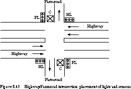
Detectors are placed along the farmroad to raise the signal C
as long as a vehicle is waiting to cross the highway. The traffic light
controller should operate as follows. As long as no vehicle is detected
on the farmroad, the lights should remain green in the highway direction.
If a vehicle is detected on the farmroad, the highway lights should change
from yellow to red, allowing the farmroad lights to become green. The farmroad
lights stay green only as long as a vehicle is detected on the farmroad
and never longer than a set interval to allow the traffic to flow along
the highway. If these conditions are met, the farmroad lights change from
green to yellow to red, allowing the highway lights to return to green.
Even if vehicles are waiting to cross the highway, the highway should remain
green for a set interval. You may assume there is an external timer that,
once set via the control signal ST (set timer),
will assert the signal TS after a short time interval has expired (used
for timing yellow lights) and TL after a long time interval
(for green lights). The timer is automatically
reset when ST is asserted."
Understanding the Specification To
understand the problem statement, a good way to begin is to identify the
inputs and outputs and the unique configurations of the controller. The
inputs and outputs are as follows:
| Input signal | Description |
|---|---|
| Reset | place controller in initial state |
| C | detects vehicle on farmroad in either
direction |
| TS | short timer interval has expired |
| TL | long timer interval has expired |
| Output signal | Description |
|---|---|
| HG, HY, HR | assert green, yellow, red highway lights |
| FG, FY, FR | assert green, yellow, red farmroad lights |
| ST | commence timing a long or short interval |
| State | Description |
|---|---|
| S0 | highway green (farmroad
red) |
| S1 | highway yellow (farmroad
red) |
| S2 | farmroad green (highway
red) |
| S3 | farmroad yellow (highway
red) |
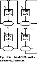
Figure 8.44 shows an initial ASM chart. It captures the basic state sequencing:
S0, S1, S2, S3, and repeat. The setting
of the outputs for controlling the lights is straightforward. To complete
the ASM chart, our major challenge is to determine the conditions under
which the state transitions should take place.
First, we should list our assumptions. We assume that
a reset signal places the controller in state S0, with the highway
green and the farmroad red. Reset should also cause the timer to commence
its timing function.
From the problem specification, the controller should
stay in state S0 as long as no vehicle is waiting on the farmroad.
Even if a vehicle is waiting, the highway is guaranteed to stay green for
the long time interval. Thus, the conditions for advancing from S0
to S1 are that TL is asserted and C is asserted. In all
other cases, the controller should remain in S0.
We show two alternative methods for representing this
transition in Figure 8.45.
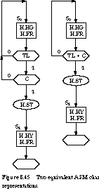
The chart fragment at the left of the figure first checks TL and then
C. If both are asserted, the ST output is asserted and the machine
advances to state S1. Unlike a program flowchart, the order in
which TL and C are checked does not matter. The decision boxes
could just as easily have been written the other way around. The fragment
at the right of the figure has combined the two decision boxes into a single
box containing the essential exit condition: TL C.
Next, let's consider the transition from S1 to
S2. According to the specification, the controller should remain
in S1 for the short time interval before advancing to S2.
The exit condition is an asserted TS signal. Otherwise, the machine stays
in S1. The chart fragment for S1 is shown in Figure 8.48.
The behavior of S3, with its transition to S0, is very
-similar.
Now all that remain are the transitions for S2,
the farmroad green state. The exit conditions are: a long time interval
has expired, whether or not any cars are still waiting, or there are no
more vehicles waiting to cross the intersection. This can be expressed as
the condition TL + ![]() . Under any other circumstances,
we remain in state S2.
. Under any other circumstances,
we remain in state S2.
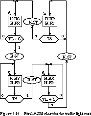
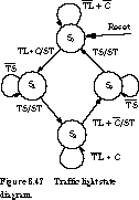
Figure 8.46 contains the completed ASM chart. ST is asserted on exiting
each state to reset the timers. For comparison, an equivalent state diagram
is shown in Figure 8.47 (the traffic light outputs are not
shown). The conditions for remaining in states S0
and S2 are less clear in the state diagram, although they are nothing
more than the complement of the exit conditions.
ABEL Description The ASM chart
for the traffic light controller combines some aspects of Mealy machines
and Moore machines. The set timer signal ST is asserted on state transitions
(Mealy behavior), while the traffic light signals
are decoded from the state (Moore behavior). Fortunately,
the ABEL language is powerful enough to describe such mixed behavior. It
describes the traffic lights in terms of combinational equations of the
current state, and asserts ST in conjunction with state transitions within
IF-THEN-ELSE statements. An ABEL description for the traffic light controller
follows:
module traffic

title 'traffic light state machine

	Joe Engineer, Itty Bity Machines, Inc.'

u1   device   'p22v10';
"Input Pins

	clk, C, RESET, TS, TL

		pin   1, 2, 3, 4, 5;
"Output Pins

	Q0, Q1, HG, HY, HR, FG, FY, FR, ST

		pin   14, 15, 16, 17, 18, 19, 20, 21, 22;
	Q0, Q1                       istype 'pos,reg';

	ST, HG, HY, HR, FG, FY, FR   istype 'pos,com';
"State registers

SREG = [Q0, Q1];

S0   = [ 0,  0];

S1   = [ 0,  1];

S2   = [ 1,  0];

S3   = [ 1,  1];
equations

	[Q0.ar, Q1.ar] = RESET;

	HG = !Q0 & !Q1;

	HY = !Q0 & Q1;

	HR = (Q0 & !Q1) # (Q0 & Q1);

	FG = Q0 & !Q1;

	FY = Q0 & Q1;

	FR = (!Q0 & !Q1) # (!Q0 & Q1);
state_diagram SREG

state S0: if (TL & C) then S1 with ST = 1

			 else S0 with ST = 0

state S1: if TS then S2 with ST = 1

			 else S1 with ST = 0

state S2: if (TL # !C) then S3 with ST = 1

			 else S2 with ST = 0

state S3: if TS then S0 with ST = 1

			 else S3 with ST = 0
test_vectors

([clk,RESET, C, TS, TL] ->

				             [SREG,HG,HY,HR,FG,FY,FR,ST])

[.X.,   1,.X.,.X.,.X.] -> [ S0, 1, 0, 0, 0, 0, 1, 0];

[.C.,   0,  0,  0,  0] -> [ S0, 1, 0, 0, 0, 0, 1, 0];

[.C.,   0,  1,  0,  1] -> [ S1, 0, 1, 0, 0, 0, 1, 0];

[.C.,   0,  1,  0,  0] -> [ S1, 0, 1, 0, 0, 0, 1, 0];

[.C.,   0,  1,  1,  0] -> [ S2, 0, 0, 1, 1, 0, 0, 0];

[.C.,   0,  1,  0,  0] -> [ S2, 0, 0, 1, 1, 0, 0, 0];

[.C.,   0,  1,  0,  1] -> [ S3, 0, 0, 1, 0, 1, 0, 0];

[.C.,   0,  1,  1,  0] -> [ S0, 1, 0, 0, 0, 0, 1, 0];

end traffic;

In this description, the state is described by the
internal registers Q0 and Q1. These are asynchronously
reset to 0 when the external RESET signal is asserted.
The equations for the traffic light outputs, HG, HY,
HR, FG, FY, and FR, are written as combinational functions of the states
in which these lights should be illuminated. For example, HG is asserted
in S0. This is written as !Q0 & !Q1
(note that ! is NOT, & is AND, # is OR). Similarly,
FR is asserted in states S0 and S1, which is written as
(!Q0 & !Q1) # (!Q0
& Q1).
The state_diagram section describes the
state transitions. The with statement associates signal changes
with state transitions. Thus, if we are in S0 and TL and C
are both asserted, we move to state S1 with the signal ST asserted.
The test_vectors section provides the verification
test cases for the state machine. The first vector verifies that the machine
will enter S0 when reset is asserted. The second and third vectors
check that the machine stays in S0 until TL and C are
asserted. Note that it is not possible to check on the assertion of ST.
In the third vector, ST is asserted just before the rising clock edge. After
the edge, the machine enters S1 while unasserting ST. The vectors
describe the state of the outputs only after the clock edge, not at the
edge.
The fourth and fifth vectors check the conditions for
leaving state S1, namely that TS is asserted. The sixth and seventh
vectors perform a similar check on S2. One of the conditions for
leaving the state is that TL is asserted, even if C is still asserted.
The final vector verifies the exit condition for S3.
When TS is asserted, we return to S0. The collection of test vectors
is not exhaustive, but it describes one possible scenario for the sequence
of events for one complete cycling of the traffic lights. Additional vectors
can be added to check other cases, such as leaving state S2 as
soon as C becomes unasserted.
Discussion This case study illustrates
the basic strength of ASM charts. They let us concentrate on the paths and
conditions we follow to exit a state. As in the leftmost chart in Figure
8.45, we can build up the exit conditions incrementally, as in a program
flowchart. Later we can combine them into a smaller number of Boolean exit
expressions, as at the right of Figure 8.45. Although it is subjective,
the description in Figure 8.46 seems to be easier to understand as an algorithm
than the state diagram of Figure 8.47.
(see
Exercises 8.29 and 8.30), could be provided to change the key
value in the register. In this way you can design the finite state machine
once, yet have it operate with any key combination. We will assume a fixed
register-based key value in this study.(when pressed,
it will assert a signal for exactly one clock period), and
the KEY-IN value is set before the operator presses ENTER. It is fair to
assume that the clock of the FSM runs much faster than human interaction
times, which are typically measured in tenths of a second. 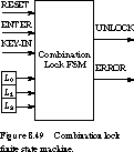
Figure 8.49 shows the final FSM block diagram.
Formal Representation Now we are
ready to enumerate the machine's states while refining the ASM chart. Let's
start by listing states that will lead to unlocking the door. We will come
back to the error conditions on a second pass.
There must be some starting state, START, that is always
entered when RESET is asserted. Since the key length is 3 bits, there should
also be one state for each key bit comparison. To enter the first comparison
state-let's call it COMP0-ENTER must be pressed and RESET must not be asserted.
This is shown in Figure 8.50.
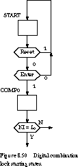
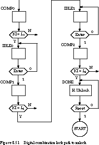
What is the condition to exit COMP0? Obviously, KEY-IN
(abbreviated KI from here on) must match L0.
You might be tempted to include ENTER, with the intention of exiting to
a state COMP1 that checks the second key bit when ENTER is asserted. However,
this would not be correct. Once we know the key bit is correct, we should
exit to an idle state to wait for ENTER to be asserted again. We
cannot check KI and ENTER simultaneously, since the operator will change
KI before pressing ENTER. And since the time between subsequent ENTER presses
could be quite long, we need to loop in some state until ENTER is pressed
again.
With the insertion of idle states, we give the set of
states for unlocking the door in Figure 8.51. We remain in the DONE state,
asserting UNLOCK, until RESET is asserted.
Our ASM chart is only partially complete. We still
have to handle cases in which the entered key bit does not match the lock
bit. A simple strategy would have all such state exits change to an ERROR
state that asserts ERROR and remains in that state until RESET. Unfortunately,
this makes it very easy to "pick" the lock, since the FSM will
assert ERROR as soon as it detects the first incorrect bit.
A better strategy is to detect errors as soon as they
happen, but to assert ERROR only after a full sequence of key bits has been
input. The structure of this part of the ASM chart is similar to that of
the unlock path and is given in Figure 8.52.
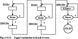
COMP0 exits to IDLE0' on error (that is, when KI
does not equal L0), COMP1 error exits to IDLE1', and
COMP2 error exits to ERROR3.
Stitching together the various ASM charts should now
be straightforward. For comparison, we give a complete state diagram for
the FSM in Figure 8.53.
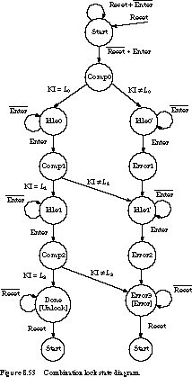
ABEL Description At this point,
you should be reasonably familiar with the ABEL syntax. Here is the description
for the combination lock finite state machine:
module lock

title '3 bit combination lock state machine

	 Joe Engineer, Itty Bity Machines, Inc.'

u1   device   'p22v10';
"Input Pins

	     clk, RESET, ENTER, L0, L1, L2, KI

	pin	  1,   2,     3,     4,  5,  6,  7;
"Output Pins

	    Q0, Q1, Q2, Q3, UNLOCK, ERROR

	pin 16, 17, 18, 19, 14,     15;
	Q0, Q1, Q2, Q3   istype 'pos,reg';

	UNLOCK, ERROR    istype 'pos,com';
"State registers

SREG   = [Q0, Q1, Q2, Q3];

START  = [ 0,  0,  0,  0];

COMP0  = [ 0,  0,  0,  1];

IDLE0  = [ 0,  0,  1,  0];

COMP1  = [ 0,  0,  1,  1];

IDLE1  = [ 0,  1,  0,  0];

COMP2  = [ 0,  1,  0,  1];

DONE   = [ 0,  1,  1,  0];

IDLE0p = [ 0,  1,  1,  1];

ERROR1 = [ 1,  0,  0,  0];

IDLE1p = [ 1,  0,  0,  1];

ERROR2 = [ 1,  0,  1,  0];

ERROR3 = [ 1,  0,  1,  1];
equations

	[Q0.ar, Q1.ar, Q2.ar, Q3.ar] = RESET;

	UNLOCK = !Q0 & Q1 & Q2 & !Q3;  "asserted in DONE

	ERROR = Q0 & !Q1 & Q2 & Q3;    "asserted in ERROR3
state_diagram SREG

state START:  if (RESET # !ENTER)

	then START else COMP0;

state COMP0:  if (KI == L0) then IDLE0 else IDLE0p;

state IDLE0:  if (!ENTER) then IDLE0 else COMP1;

state COMP1:  if (KI == L1) then IDLE1 else IDLE1p;

state IDLE1:  if (!ENTER) then IDLE1 else COMP2;

state COMP2:  if (KI == L2) then DONE else ERROR3;

state DONE:   if (!RESET) then DONE else START;

state IDLE0p: if (!ENTER) then IDLE0p else ERROR1;

state ERROR1: goto IDLE1p;

state IDLE1p: if (!ENTER) then IDLE1p else ERROR2;

state ERROR2: goto ERROR3;

state ERROR3: if (!RESET) then ERROR3 else START;
test_vectors

([clk,RESET,ENTER,L0,L1,L2,KI] -> [SREG,UNLOCK,ERROR])


 [.X., 1, .X.,.X.,.X.,.X.,.X.] -> [ START,   0,   0];

 [.C., 0,   1,  1,  0,  1,  1] -> [ COMP0,   0,   0];

 [.C., 0,   0,  1,  0,  1,  1] -> [ IDLE0,   0,   0];

 [.C., 0,   1,  1,  0,  1,  0] -> [ COMP1,   0,   0];

 [.C., 0,   0,  1,  0,  1,  0] -> [ IDLE1,   0,   0];

 [.C., 0,   1,  1,  0,  1,  1] -> [ COMP2,   0,   0];

 [.C., 0,   0,  1,  0,  1,  1] -> [  DONE,   1,   0];
 [.C., 1,   0,  1,  0,  1,  0] -> [ START,   0,   0];

 [.C., 0,   1,  1,  0,  1,  0] -> [ COMP0,   0,   0];

 [.C., 0,   0,  1,  0,  1,  0] -> [IDLE0p,   0,   0];

 [.C., 0,   1,  1,  0,  1,.X.] -> [ERROR1,   0,   0];

 [.C., 0,   0,  1,  0,  1,.X.] -> [IDLE1p,   0,   0];

 [.C., 0,   1,  1,  0,  1,.X.] -> [ERROR2,   0,   0];

 [.C., 0,   0,  1,  0,  1,.X.] -> [ERROR3,   0,   1];

end lock;
Since the UNLOCK and ERROR outputs are asserted in only one state each, the combinational logic equations for these are straightforward. The state transitions are nothing more than mapping the state charts or diagrams into ABEL's IF-THEN-ELSE syntax. The "
=="
notation represents an equality operation.test_vectors show two sequences, one
leading to UNLOCK and the other leading to ERROR. In both cases, the lock
combination is 101. In the first sequence, RESET brings us to the START
state. When ENTER is pressed, we advance to COMP0. KI is compared to L0.
Since they match, we advance to IDLE0. KI changes to 0 and ENTER is asserted.
This moves us to COMP1, where KI and L1 are compared. Since these
match, we go to IDLE1 next. KI changes to 1 and ENTER is again asserted.
This moves us to COMP2. Since KI matches L2, we enter DONE and
assert UNLOCK.